05. Connect the LED Circuit
Connect the LED Circuit
We'll start by powering the board. Then, put the resistor in place and finally the LED.
Connect the Power
Connect a jumper to one of the GND pins on J21. Checking the pinouts for J21, Pin 39 is a good choice. Connect the + rail on the breadboard to a 5V power pin on the J21 header, such as Pin 2. Connect the - rail on the breadboard . Connect a jumper to one of the GND pins on J21… looks like pin 39 should be fine. Now take a measure with your voltmeter to see what you’ve got. If it's near 5V, that’s good. Now disconnect the Jetson so there is no power while building the circuit.
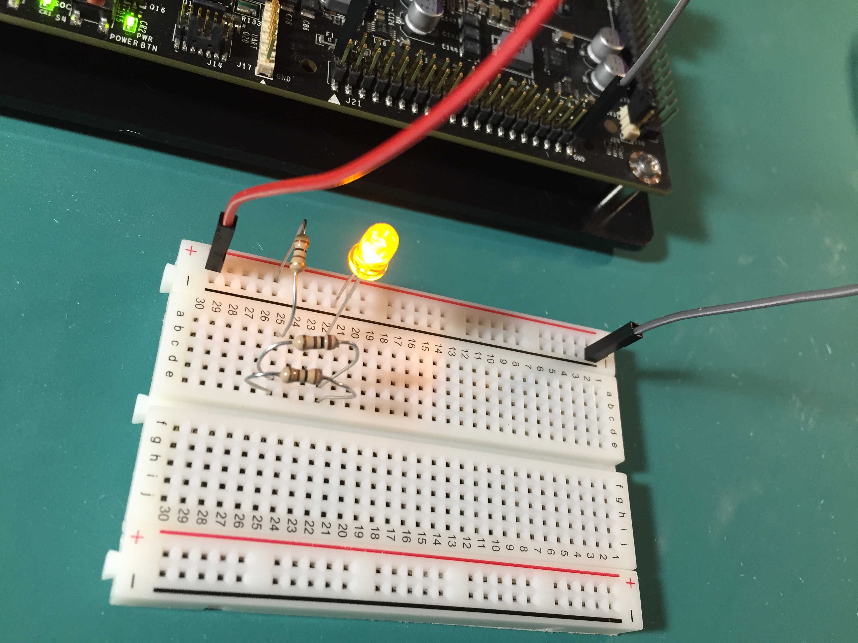
Connect the Resistors and LED
Looking at the circuit we calculated, we need the resistor (or equivalent resistor circuit) connected from the power rail to an open line on the breadboard. Then connect the anode of the diode to the same line as the other end of the resistor… that’s the longer lead of the LED. The cathode (short lead) end of the LED goes back to ground. Power up the Jetson and the light should now be on.
It should always be on as long as the Jetson is powered up, but that’s all it does. Next, we’ll create an electronic switch for the circuit using a transistor.